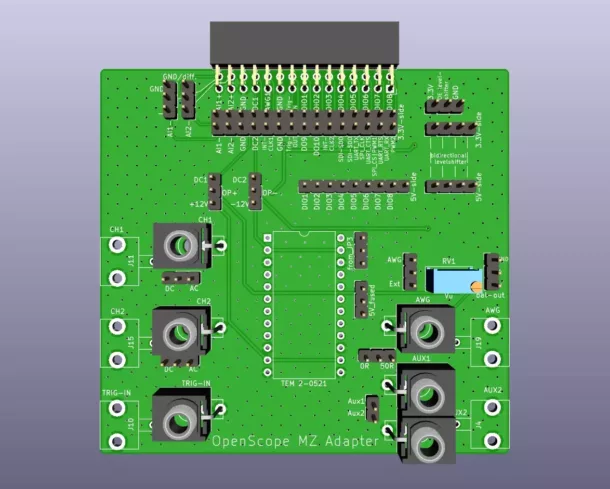
OpenScope MZ Adapter
This adapter for the Digilent OpenScope MZ allows testing of Eurorack modules and the use of probes and test leads with BNC connectors.
The measurement adapter for the Digilent OpenScope MZ can be used to perform measurements on Eurorack modules. In conjunction with LabVIEW, automated tests can also be created. The board contains matching circuits to adapt the inputs and outputs of the OpenScope to the higher voltage level of the modular system.
The board is attached to the OpenScope instead of the MTE cable. The connections are doubled on a double row pin header. The MTE cable can be connected to this. The following lists the features of the OpenScope MZ (from Digilents Reference Manual) and describes the adaptation circuits of the adapter board.
Oscilloscope
- 2 Channels
- Resolution 12-bit
- Sample Rate 6.25 MS/s
- Bandwidth 2 MHz
- Input Impedance 1 MΩ
- Voltage Range ±20V
- Max Buffer Size 32640 Samples per channel
The OpenScope has two oscilloscope channels with differential inputs (. For single-ended measurement, the two negative inputs can be jumpered to GND. The positive inputs are connected in parallel to the CH1 and CH2 BNC and mini jack sockets. Further jumpers can be used to set the coupling from DC to AC.
Arbitrary Waveform Generator
- Channels 1
- Resolution 10-bit
- Sample Rate 10 MS/s
- Bandwidth 1 MHz
- Voltage Range 3V peak-to-peak ±1.5V offset.
- Max Buffer Size 25000 Samples
- Max Current Output 20 mA
The waveform generator of the OpenScope is output with adjustable gain in parallel to a BNC and mini jack socket. The output impedance of the BNC socket can be jumped to 50 ohms. With a fivefold amplification, Eurorack audio signals (-5 V ... +5 V) can be generated. LFO signals (-2.5 V ... +2.5 V) can be realised with lower amplification. The balanced signal of the AWG is connected to a pin header; a balanced plug (XLR or TRS) can be connected via an adapter cable.
Programmable Power Supply
- Channels 2
- Output Voltage ±4V
- Maximum Power 50 mA per channel
The two programmable power sources of the OpenScope are connected to two jumpers and can be used to supply (+/-4V) the operational amplifier. In the other jumper position, the op-amp is powered with +/-12V (80 mA) from the DC/DC converter.
GPIO / Logic Analyzer
- Channels 10
- Logic Level 3.3V CMOS
- Sample Rate 10 MS/s
- Max Buffer Size 32640 Samples per channel.
- Source 7 mA
- Sink 12 mA
- Peripheral: INT, SPI, UART, 2 PWM
The digital I/O connections in 3.3V logic of the OpenScope are partly connected via bidirectional level shifters to adapt them to 5V levels. Eight level shifters are directly connected to DIO1 to DIO8. Four level shifters are freely assignable, e.g. to adapt the UART connections.
Trigger
The OpenScope has an external trigger IN and trigger OUT. The trigger IN is protected from high signal levels by a voltage divider and transistor. The trigger OUT can be adjusted via the level shifter.
Aux
Two signals can be freely connected to auxilary sockets via a pin header. Aux2 is designed as a BNC and mini jack socket, Aux1 only as a mini jack socket.
Power supply
As there is no supply voltage at the MTE connector, the adapter board must be supplied with 5V from the OpenScope pin header JP3 pin 3 and pin 2 with two wires. The 3.3V for the level shifters are generated on the board.
“OpenScope MZ” is a trademark of Digilent