
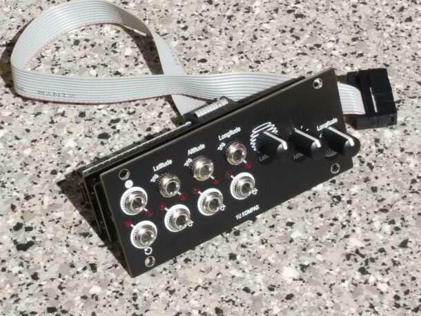
1U Kompas
1U version of Bastl Instruments Kompas Probability Trigger Generator module. Based on the Arduino Nano, for easy modification of the firmware.
This is a Intellijel format 1U variant of stziopa / Bastl Instruments' Kompas Probability Trigger Generator 3U Eurorack module. By using an Arduino Nano (original or clone), changing or completely rebuilding the firmware is very easy. You don't need a programming adapter, because the nano already contains one. For extensions and modifications, all pins are led out on pin headers like on the original Kompas module.
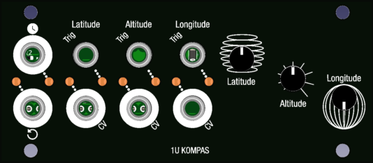
The three tracks called "coordinates" each have their own tempo and trigger output. The probability of a trigger event can be determined manually via the potentiometers or via externally fed CV. After change a new pattern is generated and played back until a new setting is made. A clock and a reset input allow synchronization with other modules.
Features:
- global clock and reset input
- 3 x 32 step pattern generators
- 3 CV inputs for coordinate modulation
- 3 trigger outputs
- 2, 5, 10ms selectable trigger length (via boot settings, default: 5ms)
- DIY and hacker friendly programmable Arduino hardware
- open source schematics and code (license: CC-BY-SA)
- available as DIY kit and assembled module
- 1U Intellijel Format
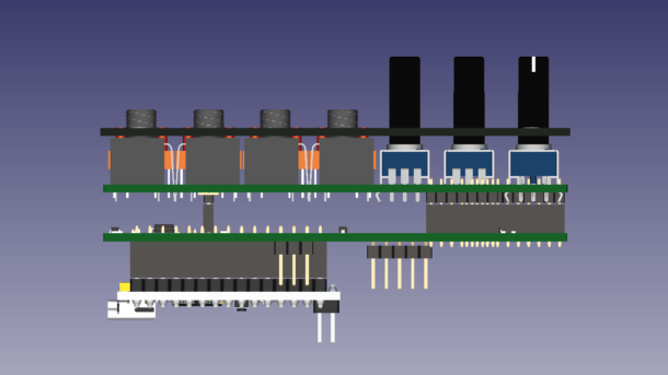
The schematic is based on the original schematic of the Bastl Instruments Kompas module. The resistors and transistors were moved to the second board. The labels have the same names. On J13 "Expansion" five of the digital inputs/outputs are also led out on a pin header. Instead of the three jumpers for LED0 to LED2, which are used to connect the LEDs to the outputs, solder jumpers are placed on the board. These can be disconnected if the pins are to be used for other purposes. In addition, +5V and GND and TX and RX from the microcontroller are also on the headers. The tips for the original Kompas module also apply here.


